What is Electrical Control Panel?


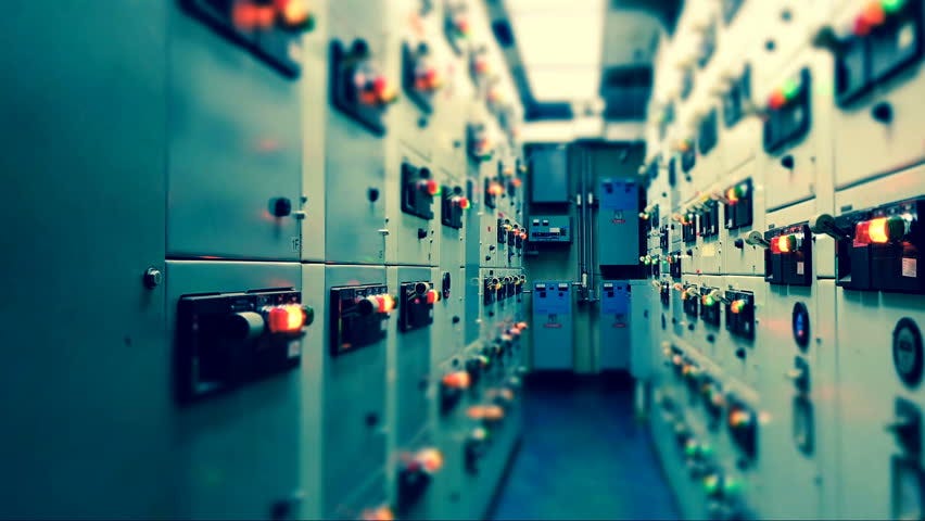
Electrical panel components control every piece of equipment in every industry. It’s difficult to describe all possible combinations because every industry and most companies have defined component preferences.
If you need to come up to speed on control panels fast, take your time. Find someone to help you, someone who knows what you’re trying to do. Start with the basics and build from there. Below are the basics.
Electrical Control Panel Descriptions
If control panels are new to you and you want to learn about them the first step is learning the terms used to describe them. What are the major descriptive categories and how is each one described? Below is an example of how to describe important control panel attributes.


1 • Safety Ratings
- 3rd Party Safety Certification = UL508A (cULus)
- Short Circuit Current Rating (SCCR) = 5kA
2 • Enclosure Ratings
- NEMA Rating: NEMA 4X Outdoor
- Material: 304 Stainless Steel
- Mounting: Wall Mount
- Door Mechanism: Lockable Handle with 3 Point Door Latch


3 • Main Power
- Incoming Power
- 480V 3 Phase through a Main Circuit Breaker
- Outgoing 480V Power
- 480V 5.0 HP Fan through a Motor Starter
- 480V 1.0 HP Pump through a Motor Starter


4 • Control Power
- 120V and 24VDC
- 480V-120V Transformer
- 120V-24VDC Power Supply
- Outgoing 120V Power
- Chemical Pump through a Power Relay
5 • Door Mounted Operator Devices
- Power
- Main Circuit Breaker Operator
- Fan
- Hand-Off-Auto Selector
- Fan Running Light
- Low Flow Light
- Recirculation Pump
- Hand-Off-Auto Selector
- Pump Running Light
- Low Flow Light
- Sump pH Meter (Signet)
- Chemical Pump
- Hand-Off-Auto Selector
- Running Light
- Tank Low Level Light
6 • Sequence of Operation
- Supply Fan
- In Hand
- Run Supply Fan
- In Auto
- Monitor Air Flow Switch to verify Air Flow above minimum Flow Rate
- Alarm and stop Supply Fan if Air Flow below desired Flow for X Seconds
- Recirculation Pump
- In Hand
- Run Recirculation Pump
- In Auto
- Monitor Water Flow Switch to verify Water Flow above specified Rate
- Alarm and stop Recirculation Pump if Water Flow below minimum Rate for X Seconds
- Chemical Pump
- In Hand
- Run Chemical Pump
- In Auto
- Monitor Chemical Tank Level Switch to verify Chemical Level above minimum Tank Level
- Alarm and stop Chemical Pump if Chemical Level below minimum Tank Level for X Seconds
7 • Remote Control Interface
- Digital (Dry Contact) Inputs
- System Enable Contact
- Digital (Dry Contact) Outputs
- System Local-Off-Remote Selector in Remote Contact
- Fan Running Contact
- Pump Running Contact
- Chemical Tank Low Contact
- Analog (4–20mA) Outputs
- pH signal from Door Mounted pH Meter (Signet)
Control panel consist of a controller. Controller may be PLC, DCS, relay or some other type. It gives digital signal input signal to the MCC panel to start the motor. Control panel works based on the PLC /DCS program or the relay logic. Instruments are normally connected to control panel. Indications for the interlocks also will be there in control panel. Nowadays single panel is used of using separate control and MCC panel.
Ease in modification of logic, reduced size, means of remote communications and advances in the technology have made PLC Automation Control Panels an edge over conventional relay based systems. Control Systems Engineers has provided PLC based Panels from PLC of Allen Bradley, Siemens, Modicon, GE Fanuc. From small I/O application to the complex I/O systems are provided by the Control Systems Engineers. Control Systems Engineers have developed communication software’s for remote communication of the PLC Panels in various different protocols. With PLC based Panels HMI/MMI are provided to provide the operator various messages and controls of the process plants touch screen MMI are provided. To effective control of the system.
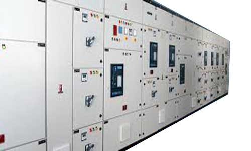
MCC PANEL


MCC stands for motor control center. It consists of feeders for motors and blowers. Feeders are designed according to the motor rating. In most of the MCCs, auto/manual provision will be there. With manual provision motors can be operated manually. In auto provision external signal is required to start the motor. The signal is given by the control panel. Indicators for the motor operation also will be present in control panel.
A motor control center (MCC) is an assembly of one or more enclosed sections having a common power bus and principally containing motor control units. Motor control centers are in modern practice a factory assembly of several motor starters. A motor control center can include variable frequency drives, programmable controllers, and metering and may also be the electrical service entrance for the building.
PCC PANELS


PCC Panels are the most essential part of electrical system of an industry from where the power of the industry is controlled. Perfect Products (India) is widely known for premium quality PCC panels designed and manufactured according to the customer specifications. Best quality switchgear and busbar are used for reliable and efficient performance.
- We manufacture PCC panels with rated current ranging from 630A to 6300A
- PCC panels are manufactured in a perfectly compartmentalized structure.
- Premium quality insulators are used to ensure safety.
- There can be a provision of space heater, thermostat and backup protection if required by customer.
- User friendly, safe and reliable
APFC PANELS


APFC Panel has microcontroller based programmable controller which switches the capacitor banks of suitable capacity automatically in multiple stages by directly reading the reactive load (RKVA) which works in the principle of VAR sensing tends to maintain the PF to 0.99 Lag. The capacitor banks may be selected in number of stages as 4/6/8 according to the load pattern. Modern power networks consists of wide variety of electrical and power electronics loads, in case of such varying loads, the power factor also varies as a function of the load requirements .So it is practically difficult to maintain consistent power factor by the use of fixed compensation i.e. fixed capacitors which shall need to be manually switched to suit the variations of the load. It can lead to situations where the installation can have a low power factor leading to higher demand charges and levy of power factor penalties. In addition to not being able to achieve the desired power factor it is also possible that the use of fixed compensation can also result in leading power factor under certain load conditions. This is also unhealthy for the installation as it can result in over voltages, saturation of transformers, maloperation of diesel generating sets, penalties by electricity supply authorities etc. It is therefore necessary to automatically vary, without manual intervention, the compensation to suit the load requirements. This is achieved by using on Automatic Power Factor Correction (APFC) system which can ensure consistently high power factor without any manual intervention. In addition, the occurrence of leading power factor will be prevented.APFC products are fully automatic in operation and can be used to achieve, consistently high power factor under fluctuating load conditions Reduced KVA demand charges, Lower energy consumption in the installation by reducing losses Preventive leading power factor in an installation.
Install APFC Panel to avoid penalties and enjoy the benefits automatically. For maintaining the power factor according to the load factor, proper capacity of capacitors is to be connected. The value of capacitors to be connected will vary with respect to load and its existing PF. There are two ways to maintain PF-
Fixing of capacitor at the load end permanently or at the mains. Generally which is recommended for the fixed load like pumps, fans etc. and it is not possible for the load which has variations in the load and PF.
The power factor can be maintained by installing Automatic Power Factor Control Panel (APFC Panel)
LT PANELS


We also provide service in cable laying services. We offer install, testing and commissioning of HT & LT cables in trenches, trays and pipes.
Cable laying services in industrial complexes, or over large distances, they are staffed by our expert technicians and engineers who perform cable preparation, jointing, termination, testing, commissioning, maintenance and troubleshooting tasks.
Cable laying services differ in terms of capabilities like may require cable laying services for low voltage (LV), medium voltage (MV) or higher voltage (HV) cables up to 33 KV.
Main Features :
- Design and conceptualization based on Client design and specifications
- Preparation of bill of quantities, tendering
- Preparation of detailed drawings, site set out
- Sourcing of material from different well known vendors
- Evaluation and submission of progress report
- Execution of planting schemes
- Total commissioning as per the request of our esteemed client
- As per client request we do testing of Panels, repairing and replacing the panels which are not in good condition
LT Panel is an electrical distribution board that receives power from generator or transformer and distributes the same to various electronic devices and distribution boards. Such panels are used in industries both for internal and external use and, therefore, they are quite rugged to withstand different climatic conditions.
Our LT panels are designed to work with low electricity consumption that makes them cost effective
HT Panel is like LT Panel except that it is used for high tension cables.
0 Comments